
In the last post, I finished installing ROS2 Jazzy. This time, I got into writing my first node for real, and since I had some time left over that same day, I also worked through an STM32 PWM LED example.
Table of contents
Open Table of contents
- 1. Sorting out core ROS2 vocabulary
- 2. First talker node — publishing on the chatter topic every second
- 3. A standard message —
geometry_msgs/Twist - 4. listener — receiving
/cmd_veland computing left/right wheel speeds - 5. A quick break — STM32 PWM LED example
- What I did today
- Next steps (once the USB-UART converter arrives)
- Things to study further
- Retrospective
1. Sorting out core ROS2 vocabulary
Before diving in, I went over the terms that keep showing up. Words like talker and chatter appear a lot — this is just convention from the official ROS tutorials. talker / listener are the example node names, and chatter is the example topic name.
| Term | Meaning |
|---|---|
| Node | An independently running process |
| Topic | A communication channel between nodes (name + message type) |
| Publisher | The side that sends messages to a topic |
| Subscriber | The side that receives messages from a topic |
| Message | The unit of data flowing through a topic (has a fixed type) |
This was my first time with ROS2 itself, but publish / subscribe is a pattern I’ve dealt with plenty in MQTT work, so it wasn’t hard to understand.
Official ROS2 packages have standard message types split by purpose (e.g. std_msgs, geometry_msgs, sensor_msgs…). Each package contains messages suited to its own domain.
2. First talker node — publishing on the chatter topic every second
Since this was for learning, I started with a Hello World-level example.
ros2 pkg create --build-type ament_python my_agv_pkg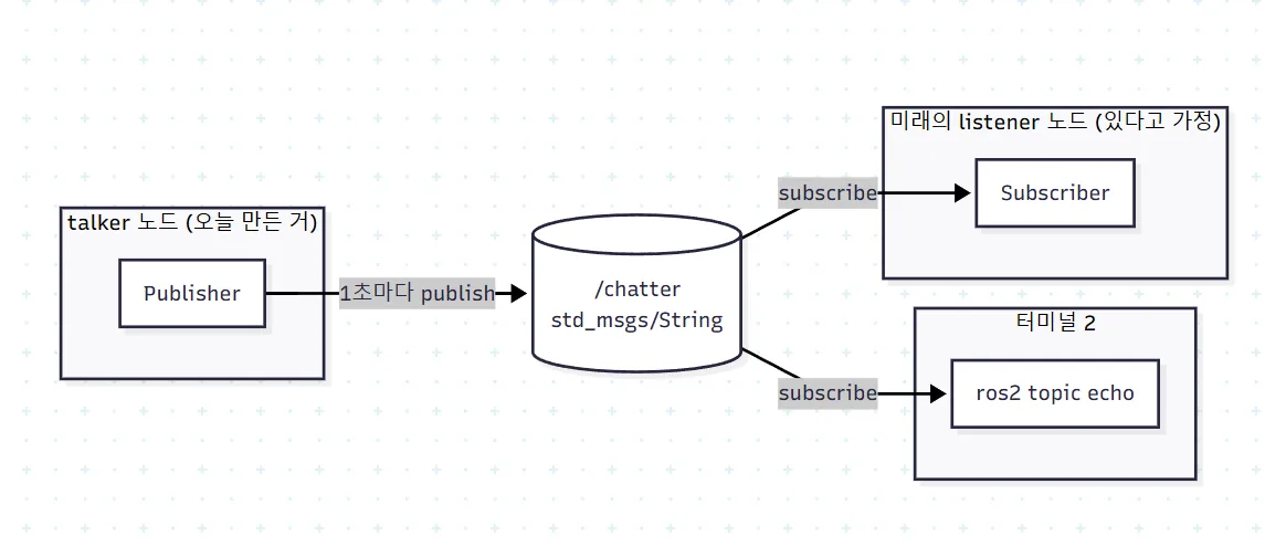
I created a talker node that sends “Hello AGV” to the chatter topic every second.
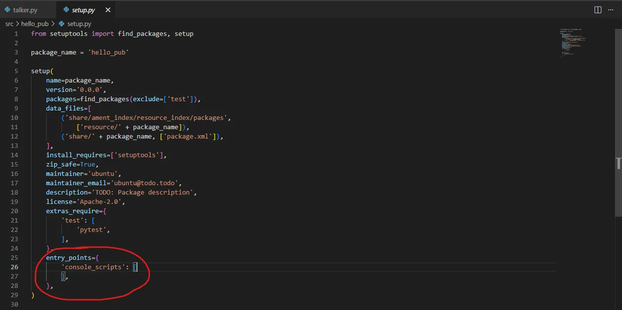
Then I had to register an entry point in setup.py so ROS2 could run the node via ros2 run.
After that, I built with colcon build.
Why do I need
source install/setup.bash? After building, you need to source it so the current shell recognizes the newly added package. The setup.bash script exports environment variables likeAMENT_PREFIX_PATH.
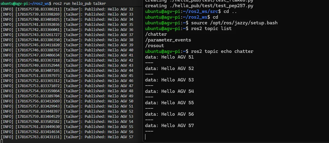
I listened on the same topic from another terminal and confirmed messages were flowing in every second.
3. A standard message — geometry_msgs/Twist
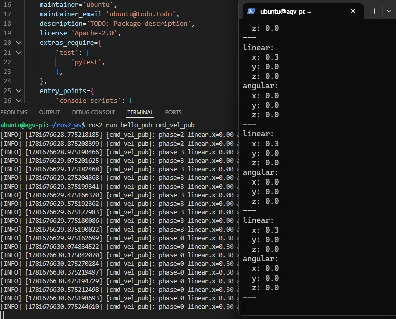
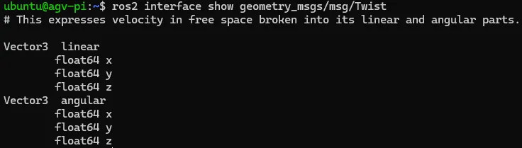
Next, I used the geometry_msgs/Twist type directly. This is a standard message carrying a robot’s linear and angular velocity, and it’s basically the de facto standard for mobile robot control.
The example itself is similar to talker, but the meaning is different. To actually move motors based on this message, you need a separate motor control node — I’ll build that on the STM32 side. For now, I just published the message and checked the flow with ros2 topic echo.
I also checked the structure of the message type.
Publishing quickly without a build — ros2 topic pub
Building and running a node every time you want to test something is heavy, so there’s also a way to publish directly from the terminal:
ros2 topic pub /cmd_vel geometry_msgs/msg/Twist "{linear: {x: 0.5}, angular: {z: 0.2}}"→ Useful for verifying topic behavior or debugging a listener.
4. listener — receiving /cmd_vel and computing left/right wheel speeds
This is the most meaningful part of today’s log. I wrote a Python simulation that receives the Twist message on /cmd_vel and converts it into left/right wheel speeds.
This is the Python version of code I’ll later implement in C on the STM32.
Differential drive kinematics:
left  = linear.x - angular.z * (wheel_separation / 2)
right = linear.x + angular.z * (wheel_separation / 2)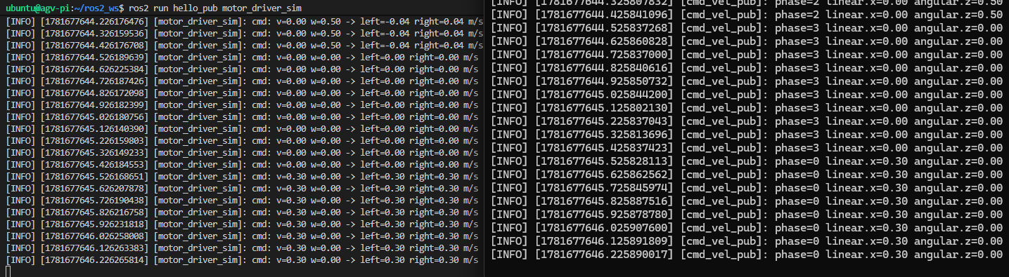
The listener received the message sent via ros2 topic pub and computed the left/right speeds. I could simulate behaviors like moving forward (linear.x > 0) and turning left (angular.z > 0). Next, the STM32 will do the same job.
5. A quick break — STM32 PWM LED example
That’s it for the ROS side today. I had some time left, so I warmed up with an STM32 PWM LED on/off example. I’ve done this plenty before, but it was good for getting a feel for PWM again.
Where I got stuck in CubeMX
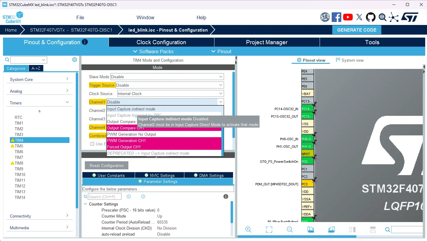
At first, the PWM Generation CH1 option was grayed out in the timer settings. After I assigned PD12–PD15 to TIM4’s respective channels in the pinout section first, the PWM Generation option showed up properly.
Calculating Prescaler and Counter Period
Goal: 1kHz PWM with 1000 steps of resolution.
| Parameter | Before → After | Reason |
|---|---|---|
| Prescaler | 0 → 83 | To get a 1MHz timer clock: TIM4_clk / (Prescaler+1) = 84MHz / 84 = 1MHz |
| Counter Period (ARR) | 65535 → 999 | For 1kHz PWM frequency + 1000 resolution: 1MHz / (ARR+1) = 1MHz / 1000 = 1kHz |
Trade-off: A larger Counter Period improves resolution but lowers frequency. A smaller one raises frequency but reduces resolution. I balanced it at 1kHz/1000 steps to fit the goal (smooth, flicker-free LED dimming).
Result — cycling LEDs
I modified main.c so the PWM duty cycle rises and falls in sequence across PD12 → 13 → 14 → 15.
What I did today
- Sorted out core ROS2 vocabulary (Node / Topic / Publisher / Subscriber / Message)
- Wrote my first talker node and confirmed publishing on the
chattertopic - Published & echoed
/cmd_velusinggeometry_msgs/Twist - Built a listener that receives
/cmd_veland converts it to left/right wheel speeds (Python version, will be ported to STM32 C later) - Configured STM32 TIM4 PWM (1kHz / 1000 steps) and confirmed LED cycling
Next steps (once the USB-UART converter arrives)
- Solder the USB-UART converter and verify UART communication (Pi 5 ↔ STM32)
- Wire up the motor driver and get the first motor spinning
- First integration: sending the ROS2 listener’s left/right speed output to the STM32 over UART
Things to study further
1. ROS2 middleware (DDS)
- Why ROS1 (TCP/UDP based) moved over to DDS (Data Distribution Service)
- How topic publishing gets automatically discovered (multicast-based)
- QoS (Quality of Service) settings — Reliable vs Best Effort, History depth, etc.
2. The 6 degrees of freedom in the Twist message
linear.x/y/z+angular.x/y/z= 6 DOF- Wheeled robots typically only use
linear.x(forward motion) andangular.z(yaw rotation) - Robots with free 3D movement, like drones, use all 6 degrees of freedom
- For wheeled robots with omni-wheels or mecanum wheels,
linear.yis also added
3. Refining differential drive kinematics
- The limits of the simple formula
left/right = lin ± ang * (L/2) - Real-world calibration for wheel slip and base width (
wheel_separation) - Closed-loop control (PID) using encoder feedback
- Odometry — estimating position from wheel rotation data
4. Going deeper into STM32 PWM
- Common PWM frequencies beyond 1kHz — motors: 10–20kHz (to avoid audible noise), LED dimming: 1kHz or higher is enough
- Dead time — the delay needed to prevent short-through when outputting complementary PWM on a motor H-bridge
- DMA + PWM — playing back patterns (LED matrices, WS2812, etc.) without burdening the CPU
5. UART → RS485 conversion
- The core topic of the next post. The difference between UART (point-to-point) and RS485 (multi-drop)
- How transceiver ICs like the MAX485 work (driver enable, half-duplex)
- Industrial standard protocols — Modbus RTU commonly runs on top of RS485
Retrospective
The highlight of today was the moment the left/right values were actually computed in the ROS2 flow from talker → /cmd_vel → listener. Something that had always felt abstract — “how does an autonomous robot receive commands” — became concrete through a single line of Twist message. Porting the same logic to C on the STM32 side is the core task for the next post.
I’m starting to feel like this series is settling into a track. Post 1 (setup) → Post 2 (first node) → Post 3 (integration) — it’s flowing together naturally.