
In the last post, I got through the first ROS2 node and STM32 PWM. Today, the USB-UART converter still hadn’t arrived, so I couldn’t push forward there. Instead, I did what I could on the hardware side. Zero lines of code today — just soldering, magnets, and voltage checks.
Embedded work really does eat up money. I went to Daiso the other day, and today I went again to buy things I forgot.
Table of contents
Open Table of contents
- 1. Rocker Switch Continuity Test — DPDT Bipolar Cutoff
- 2. Battery + Rocker Switch Wiring Plan
- 3. Soldering — My Rusty Hands Make a Comeback
- 4. Battery Voltage Measurement — 10.61V
- 5. Ordering More Parts — a Week’s Wait
- 6. Attaching Neodymium Magnets for Hall Sensors to the Wheels
- What I Did Today
- Up Next
- Things to Study Further
- Reflection
1. Rocker Switch Continuity Test — DPDT Bipolar Cutoff
First, I fixed my multimeter and ran a continuity test on the rocker switch.
At first, I read it simply as this:
- I side ON → 5, 6 connected
- II side ON → 1, 2 connected
- OFF → not connected
I thought I was done, clean and simple, but the AI next to me was suspicious, so I checked again. Here’s what was actually happening:
- I side ON → 2-3 connected, 5-6 connected (both poles at once)
- II side ON → 1-2 connected, 4-5 connected (both poles at once)
- OFF → not connected
I almost stopped after checking just one pole. This is a DPDT (Double Pole Double Throw) bipolar cutoff structure — when switched to one direction, both poles connect at the same time. “Bipolar cutoff” means cutting both the + and − lines simultaneously, which is safer.
If the AI hadn’t pointed it out a second time, I might have wired it based on only one pole. This is exactly where the weakness of working solo shows up.
2. Battery + Rocker Switch Wiring Plan
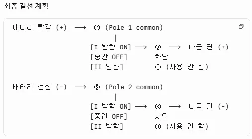
I hand-drew how to connect the battery and rocker switch. The input is the battery’s + terminal, and the output goes to the load side — STM32, motor driver, etc.
3. Soldering — My Rusty Hands Make a Comeback
I finally managed to finish the soldering. Maybe it’s because it had been a while since I last soldered, or because I’m not used to soldering at home, but on top of already having clumsy hands, I barely finished it while sweating buckets.
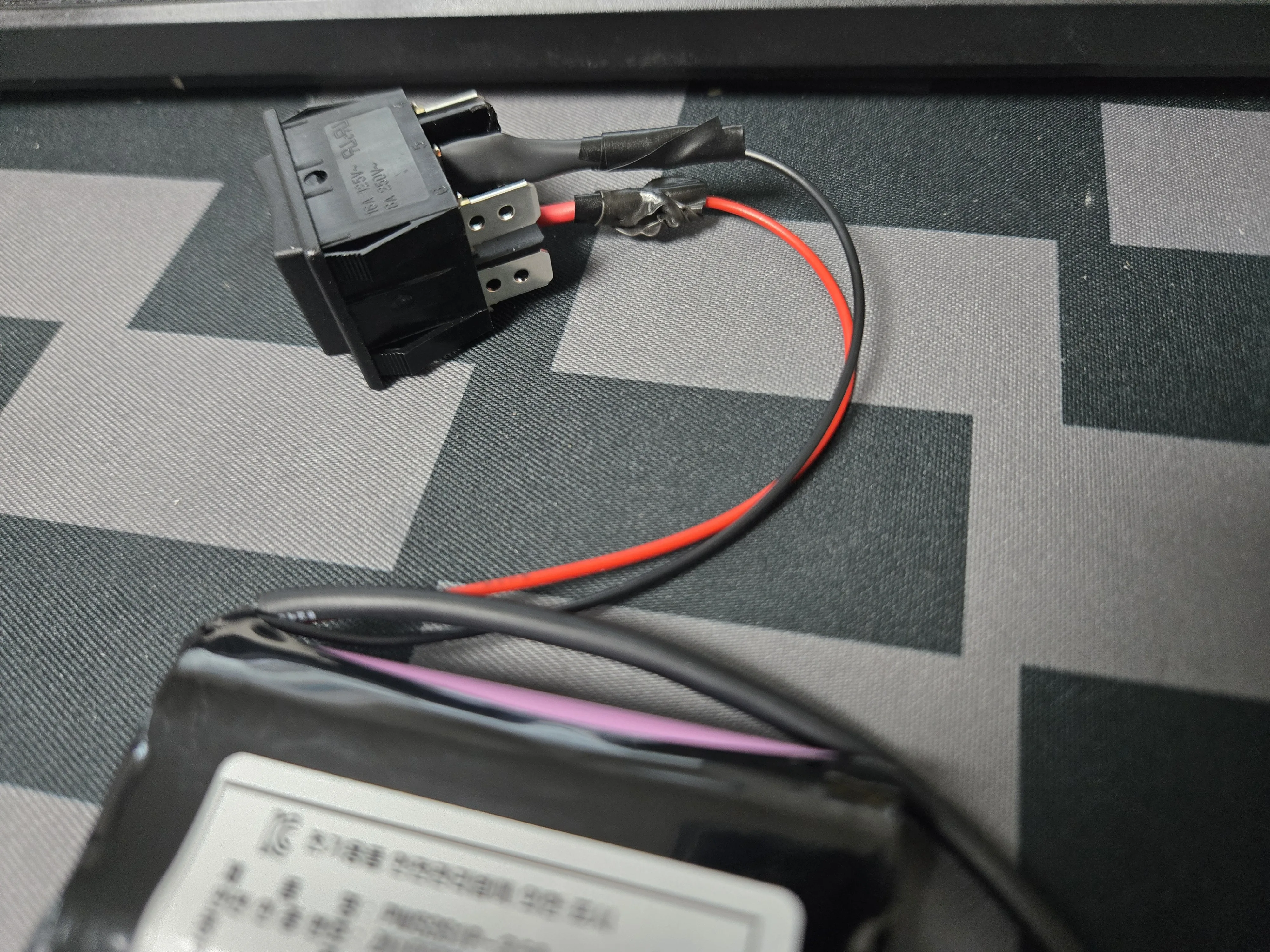
4. Battery Voltage Measurement — 10.61V
Measuring with a multimeter, I got 10.61V (couldn’t take a photo of the multimeter since I only have two hands).
Looking it up, a full charge is 12.6V, and shipping at 50% charge is apparently normal. Batteries are intentionally shipped at half charge for storage and transport safety. 10.61V is within the normal range.
5. Ordering More Parts — a Week’s Wait
Next, I need to connect the switch’s output side to the load, which means buying more cable. Hardware work is already draining, but not being able to move forward because of parts shopping is genuinely frustrating.
Here’s what I ordered this time:
- Fuse holder
- Mini fuse
- Terminal block
- AWG20 silicone cable
The fuse holder and mini fuse were hard to find, and since they’re shipping from overseas, they’ll arrive in a week. In the meantime, I decided to work on something else.
6. Attaching Neodymium Magnets for Hall Sensors to the Wheels
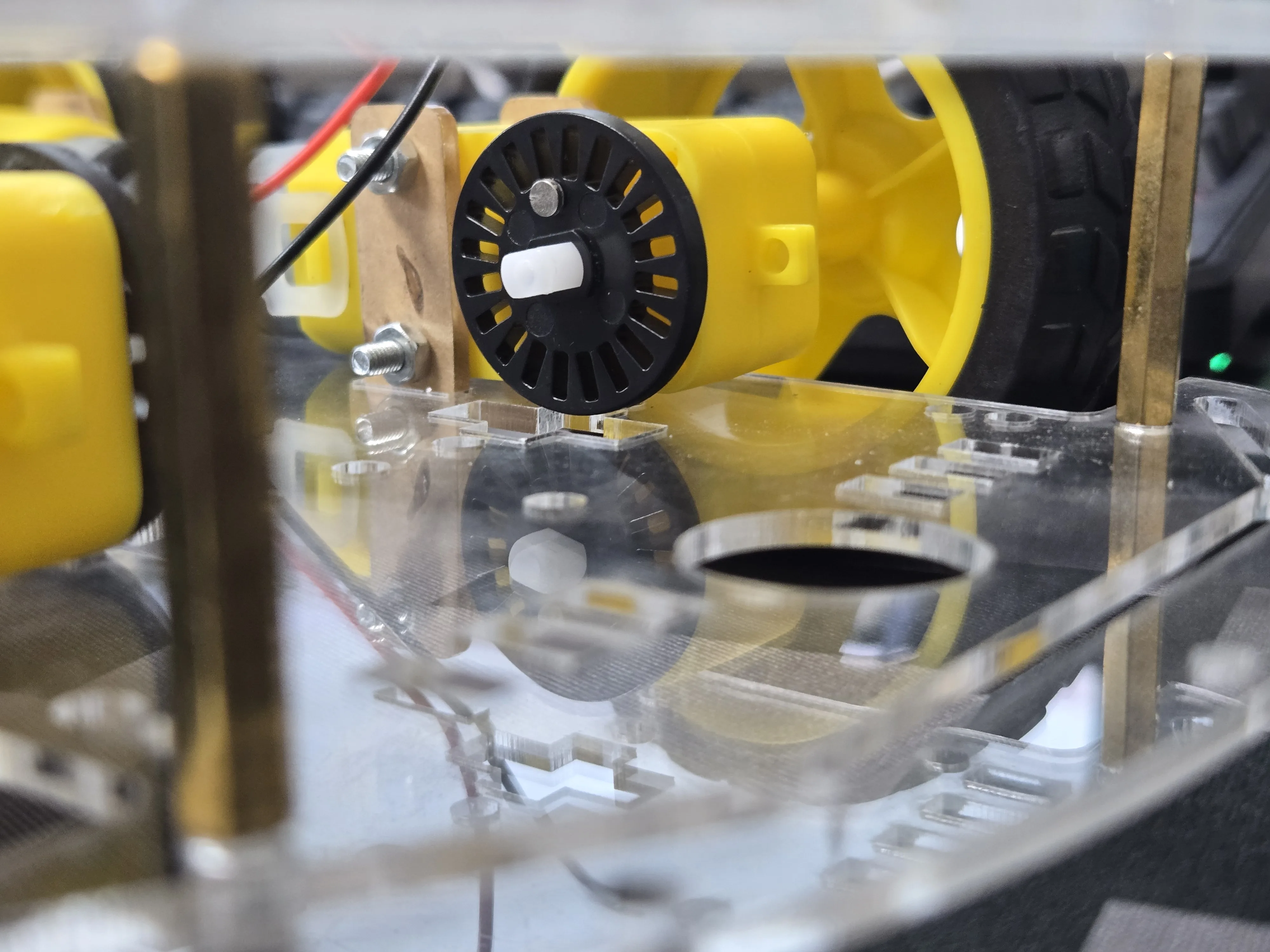
Since the USB-UART converter still hasn’t arrived, I moved on to something else. Attaching a small neodymium magnet to the inside of the wheel.
First, What a Hall Sensor Actually Is
Since I didn’t know the principle behind hall sensors, I had no idea where the magnet was supposed to go. Here’s the summary:
- Hall sensor = magnet detector
- When a magnet gets close → output signal goes LOW
- When the magnet moves away → output signal goes HIGH
Using this, I attach a small neodymium magnet inside the wheel and place the hall sensor next to the wheel. Every time the wheel completes one rotation, the magnet passes by the sensor once, so the count increases. It works the same way as a pedometer. From this, you can get:
- Distance measurement (wheel circumference × number of rotations)
- Speed estimation (count per unit time)
- Position estimation (calculating rotation angle from the difference in left/right wheel counts — differential drive odometry)
Ultimately, this single magnet becomes the starting point for the data source that will populate ROS2’s /odom topic.
The Magnet Stuck to My Tweezers, and I Was Confused
The neodymium magnet was so small that I figured I’d need tweezers to pick it up, but the magnet just stuck straight to the tweezers. I was caught off guard. Luckily, the adhesive’s grip was stronger than the magnetic pull between the magnet and the tweezers, so I worked around it by applying adhesive to the magnet while it was still stuck to the tweezers, then transferring it onto the wheel.
What I Did Today
- Rocker switch continuity test — re-confirmed the DPDT bipolar cutoff structure (with help from AI)
- Battery + rocker switch wiring plan + soldering
- Checked battery shipping voltage (10.61V → normal for 50% charge)
- Ordered more parts (fuse holder, mini fuse, terminal block, AWG20 cable, one week overseas shipping)
- Attached neodymium magnets to the inside of the wheels (preparing for hall sensor + encoder work)
Up Next
- Once the USB-UART converter arrives, verify UART communication (Pi 5 ↔ STM32)
- Wire up the hall sensor + get the first rotation count reading
- Organize the circuit diagram (right now it only exists in my head + notes)
Things to Study Further
1. What DPDT Bipolar Cutoff Means
- DPDT = Double Pole Double Throw — a switch that throws two poles (contact pairs) to one of two sides simultaneously
- Bipolar cutoff = cutting both the + and − lines at the same time → safer than cutting just one side (ensures clear electrical isolation)
- More commonly used in AC circuits, but also used in DC for motor/battery cutoff
- Summary of SPST / SPDT / DPST / DPDT differences — Wikipedia
2. Parallel Wiring on the Output Side — Everything Meets at One Point
Since I didn’t know how to wire things, I initially imagined splitting one wire into three like an org chart, but that’s not it — it’s actually about everything converging at a single point.
Take our project as an example: say there’s 1 input cable and 3 output cables. You gather and twist together the exposed copper strands of all 4 cables at a single point. Then you solder them, so all the strands become one mass, forming a parallel connection.
I had pictured “parallel means splitting from one point,” but the idea of implementing parallel by bundling everything together at one point felt interesting somehow. I also looked at some blog posts about it, and it felt almost like art.
Reference: Parallel wire connections — Nano Airtec blog
3. The Hall Effect and Types of Hall Sensors
- Hall effect principle — inside a magnetic field, a voltage develops perpendicular to the direction of current flow through a conductor
- Sensor output types:
- Digital (Latch / Switch) — like the A3144. Magnet close = LOW, magnet away = HIGH
- Linear (Analog) — analog output proportional to magnetic field strength
- Unipolar vs bipolar — which pole (N or S) the sensor responds to
- What we’ll use is digital unipolar (A3144 series) — for rotation counting
4. Why Lithium Batteries Ship at 50% Charge
- Storing at full charge (100%) for long periods causes electrolyte breakdown + shortened cell life
- Storing at 0% risks self-discharge dropping below the cut-off voltage, causing permanent damage
- So 30-50% is the storage sweet spot. Air transport regulations also cap it at 30% or below
- After arrival, charge to full soon and start using it
Reflection
Today was a zero-lines-of-code, hands-only day. It’s also a day that clearly exposed one of the downsides of embedded side projects — when a single part doesn’t arrive, the next step is completely blocked. With pure software, one npm install line can move you to the next area, but with hardware, you have to wait a week.
Still, the track is naturally following the layers of an autonomous robot — AGV Post 1 (setup) → Post 2 (first node) → Post 3 (power/sensor hardware). The next post will likely cover the first integration after the USB-UART arrives: passing left/right speed commands from the ROS2 listener to the STM32.